The Concept
New Fusion Concept Allowing Aneutronic Fusion with High Beta
For over 70 years of fusion development Tokamak now is the most well studied concept.
Simply Tokamak can be described as:
Toroidal vacuum chamber with:
transformer for which plasma is a secondary winding drives an inductive current along the toroidal axis in an equatorial plane of torus by varying of magnetic flux through that plane 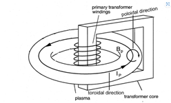 Taken from [1]
- Ip is the plasma current driven by transformer (flows in toroidal direction)
- Bp is the poloidal field produced by the plasma current
Set of toroidal coils wound around vacuum chamber producing a relatively constant toroidal magnetic field 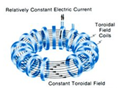 Taken from [2]
Limitations of Tokamaks [3]
- The density limit. For a given value of the plasma current, the particle density cannot exceed a certain limit, which increases as the current increases. Once the density limit is exceeded, the plasma tends to develop instabilities which cause it to shut down.
- Current limit. For a given value of the toroidal magnetic field, the plasma current that can be induced has an upper limit that cannot be exceeded and that increases with increasing magnetic field. Once this limit is exceeded, the plasma develops very fast instabilities which cause it to shut down.
- Pressure limit. This is the value of the maximum pressure of the plasma for a given value of the magnetic field. Once the limit is exceeded, the plasma column tends to deform macroscopically and suddenly extinguish the plasma.
Not going in depth of theory – only some points:
- At a given temperature the density n is higher at higher current Ip
- Plasma reactivity curve has a maximum at higher temperatures than that Tokamaks run today (30 keV for DT reaction vs. achievable today 10-15 keV). For aneutronic DHe3 reaction the maximum lays at unbelievable today 150 keV.
- Power density (the power released from the unit of volume) is proportional to n2
Running Tokamak with high current (15 MA is projected for ITER) and reasonable/achievable today density (n of order 1020 m-3) and temperature (T of order 10 keV), we need very strong toroidal magnetic field to maintain a stability. E.g. ITER has 18 toroidal field coils weighing 310 tons each. That is because to maintain the safety factor q ≥ 2 and and β (the ratio between plasma pressure and magnetic pressure of toroidal field) is around 2.5% (*spherical tokamaks allow higher value of β).
Toroidal field in Tokamaks provides only passive stabilization factor – not making itself any contribution in heating process or compression (pinch) process.
Conclusions:
Today’s Tokamaks run at:
- High safety factor q
- Low β (while power density is proportional to β 2)
- Non-optimal temperature
and are forced to be very large in dimensions with very large toroidal magnets. The achievable temperature of 10 keV order does not allow us even to think on aneutronic reactions.
Our proposal
1. To build the reactor similar to Tokamak, but in which the toroidal field magnets also are fed with time dependent current – TOROIDAL FIELD VARIES FROM ZERO TO THE CERTAIN Btmax
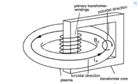
Does not differ Tokamak principally
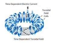 Differs from Tokamak in which Toroidal Field is constant
The principal difference from Tokamak is only in that in our proposal Toroidal field is time dependent, while in Tokamak – constant
As result, unlike Tokamaks, where only one type of inductive current flows, we will get two types of inductive currents:
- One current Iz flows in toroidal directions producing poloidal field Bθ
- The second Iθ flows in poloidal direction producing toroidal field Bz
And such a configuration stops to be a Tokamak – that is a TOROIDAL SCREW PINCH.
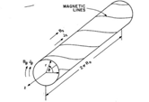
*Vacuum chamber in our proposal should be nonconductive
2. To puff to the vacuum chamber the reacting gas (e.g. equimolar mix of Deuterium an He3)
3. To apply a rather weak constant “vertical” (perpendicular to equatorial plane of torus) “betatron type” magnetic field

4. To inject into vacuum chamber two spices of ions with different q/m (where q is charge of ion and m is a mass of ion) in such a manner that both ion beams will have approximately the same gyroradius – approximately equal to major radius of torus
So, the difference of q/m and the condition for ions to have an approximately the same gyroradius will give us the difference in their velocities automatically.
For example, we can inject two intense ion beams:
- He3 – 5.5 MeV
- D – 2 MeV
Where faster He3 ions will pass through slower D ion beam.
But initially their center of mass collision energy may not be sufficient for fusion. For example, for mentioned above ion injection energies their center of mass collision energy will be:
- 138.7 keV
This value of collision energy is sufficient for fusion, but fusion cross section curve has a maximum at about 300 keV (above we stated that the maximum of reactivity curve of DHe3 reaction lays at 150 keV for thermal plasma, while here we need collision energy in a center of mass system – and cross section curve has maximum at about 300 keV)
For making a resulting plasma quasineutral we also propose at this stage to inject into the vacuum chamber some low energy electrons (“electron rain” – academician Budker’s term) [4]
In fact, we will get two unidirectional currents that will attract each other magnetically and space charge of which will be neutralized by their transport in a background plasma.
This configuration is needed to produce high energetic charged particles - products of fusion reaction of mentioned ion spices (protons and alpha particles in case of D and He3 beams) which will multiply the energy "pumped" into injection.
4a. Option
As an option may be also considered the injection of relativistic electron beam with the same gyroradius.
For example, for mentioned above ion injection energies the condition for electron beam to have the same gyroradius gives us an electron energy about:
- 85 MeV
This relativistic electron beam will have the opposite direction to those the injected ions have (the third unidirectional current).
And will provide an opportunity of very intense pinch even in case if positive space charge of ions will not be fully neutralized. Budker [5] has theoretically studied the behavior of similar configuration and came to conclusion that such an electron beam should improve stability thanks to Bremsstrahlung damping transverse oscillations/instabilities.
5. To switch-on both types of magnetic systems of the reactor and to rise both magnetic fields to their maximum value in dozens of milliseconds order duration.
5a. Time dependent betatron type magnetic field will accelerate two spices of ions injected at stage “4”.
Once initially those ion spices had an approximately the same gyroradius, during acceleration they will keep the same gyroradius (in case if the field will fit to typical “betatron condition 2:1”).
Accelerated passing through each other two coaxial unidirectional ion beams keeping a gyroradius the same will increase the difference in their velocities thus increasing center of mass collision energy increasing the probability of fusion.
Fusion products of those beams (proton and alpha particle in case of use D & He3 beams) will be confined by the magnetic field as both are charged particles and will heat up the plasma more effectively than all known before heating methods.
5b. Time dependent betatron type magnetic field also will drive a mega-ampere order toroidal inductive current in a background plasma
5c. Time dependent toroidal magnetic field will induce a poloidal current in a background plasma
Expectations
We have examples of running toroidal screw pinch devices in 1960-70th [6] They ran at:
- q – 0.75-1 (vs. 2 typical for Tokamaks)
- β – 25-65% (vs. 2.5% typical for Tokamaks) *Spherical Tokamaks have an opportunity to run at higher β but have other limitations instead
- fast aneutronic fusion products generated by passing through each other coaxial unidirectional ion beams will be confined by magnetic fields and will heat up a background plasma very effectively
Visible problems not existing in Tokamaks and how to overcome
Beams injected into background plasma and also one faster ion beam passing through another slower one unidirectional and coaxial will inevitably be subjected of two following types of instabilities:
- Two-stream instability
- Beam filamentation instability
Mitigation of both mentioned above types of instabilities [7] [8] are conducted by:
- To make beams not mono-energetic – giving to beams a certain spread in velocities (Landau damping will be observed)
- Strong toroidal magnetic field mitigates both mentioned above types of instabilities
But initially in our proposal we will not have toroidal magnetic field at all – initially Bt0=0
And the condition to have a strong toroidal magnetic field when injected ion beams will meet each other to make a proposed configuration – passing through each other coaxial unidirectional ion beams – forces us to provide an opportunity of a certain “timing”.
For example, we have a toroidal vacuum chamber with:
- major radius R – 4.2 m
- minor radius a – 2 m
*That is rather big vacuum chamber – that is bigger than JET (R=3m, a=1.25m) and smaller than ITER (R=6.2m, a=2m)
Let’s say that like ITER we have 18 toroidal field magnets and therefore 18 gaps between them.
We can inject the ion beams not along centerline of torus but e.g. inject them at a certain distance from centerline along the circle – e.g. at r=1.5 m equidistant to centerline.
When then toroidal field magnets will be switched on, the induced by them electromotive force in poloidal direction will drive those beams forcing them to rotate around the centerline of torus.
Magnetic field then will act on those rotating beams thus directing them toward to centerline where all 18 beams will meet each other and will create a proposed above configuration.
To inject mentioned 18 beams to different orbits will give us required spread in velocities automatically.
Along the way, the described rotating 18 beams will ionize the gas located inside the torus circuming by them with (our example R=4.2m, a=2m, injection radius r=1.5m) a minor radius of 1.5 m and carry it along with them.
As a result, we get a poloidal rotation of plasma.
And that would be also good for confinement [10] – ballooning instability will be less accountable for our proposal thus allowing us to expand a density limit.
Power supply & energy conversion
Both types of magnetic systems (poloidal and toroidal) will store a huge amount of energy when they produce maximum field.
For example, in ITER:
- 18 toroidal magnets in a volume of about 1200 m3 (plasma volume 840 m3) store an energy 41 GJ
- Central solenoid – about 6 GJ
- Set of poloidal field coils – about 4 GJ
Total: about 51 GJ
And in our proposal the energy stored in magnetic fields should have a comparable value.
While both types of fields are time dependent and should have the rise time of dozens of milliseconds.
Let’s say that:
- poloidal field rises from injection value to its maximum in 20 milliseconds
- toroidal field rises from zero value to its maximum in 50 milliseconds
And this leads us to very high powers have to be applied to provide these rise times – terawatts order
We propose to use Superconducting Magnetic Energy Storage SMES (inductive energy storage) for power supply.
- At a compressing stage the part of energy stored in SMES flows to the magnetic systems of the reactor through the certain time dependent resistive element which controls the rise time of magnetic fields on both systems of the reactor (poloidal and toroidal)
- At an energy release stage when plasma expands against decaying magnetic fields thus inducing there in magnetic systems of the reactor an electromotive force, energy will flow back into SMES. Excess energy will be absorbed by time dependent resistive elements which will control currents and therefore magnetic field decay time.
*As a time dependent resistive element we propose to use e.g. set of water electrolyzers controlled by high current thyristors.
In this case the excess energy released by the reactor we will get in a form of hydrogen.
New Instabilities Mitigation Method
"Plasma instability is a region where turbulence occurs due to changes in the characteristics of a plasma (eg. temperature, density, electric fields, magneti fields)."
Past experiments of Toroidal Screw Pinch (e.g. SPICA device) or Toroidal Theta Pinch produced poloidal currents in plasma with low inductance magnets being fed with capacitor bank.
While in our proposal should be magnets with high inductance being fed from inductive energy storage with on order of magnitude inductance than reactor's magnets have and also resistive elements (e.g. water elecrolysers) should be included in power supply circuits.
High inductance of magnets in the reactors causes significant eddi currents induced when any perturbation in plasma will occur.
While the resistive elements will dissipate the significant part of mentioned above eddi currents' energy.
We could not find any mention of such a method of mitigation of instabilities in thermonuclear plasma.
Conclusion
Our proposal is very similar to e.g. US Patent “Pulsed high beta fusion reactor” [9] issued by US Atomic Energy Commission in 1972.
But there is described a toroidal theta pinch, while our proposal is a toroidal screw pinch – both they are pulse high β approaches.
Both these approaches have been studied well in 60-70th of past century – here is not any of our novelty.
Our novelty is only in plasma initialization (reacting gas pre-ionization) and heating method by preliminary injected into the reactor chamber passing through each other unidirectional coaxial ion beams which thanks to energy multiplication due occurring there aneutronic fusion should be much more effective than all known today other heating methods – faster and more energy efficient.
In past century experiments β value of 25-65% has been achieved, but with insufficient for any fusion reaction (even for DT) temperature (no more than 1 keV order), while our approach will allow us to heat up plasma to temperatures even sufficient for aneutronic reactions (e.g. DHe3)
For example, ITER using DT fuel is projected to produce 500 MW of fusion power from 840 m3 plasma (595.2 kW/m3 power density) at β=2.5%. Increasing β value to 50% (20 times higher), we need only 2 times stronger toroidal magnets (10.5 T vs. 5.3 T) to achieve the same power density on DHe3 fuel.
Which is quite feasible as right now Commonwealth Fusion Systems builds a conventional tokamak with on axis toroidal field 12.2 T [11]
But to build conventional tokamak running on DT fuel, compact in size, with high fields and thus providing about 12 times higher power density than ITER provides, does not seem us reasonable. As well engineered ITER is designed for neutron load for the first wall not exceeding 0.8 MW/m2, while in SPARC this parameter will be much higher (about 3.3 MW/m2) and obviously critical components of the reactor will not have lifetime long enough for commercial application. Also SPARC is designed to run at even lower β value than ITER. SPARC seems more as a demonstration of capabilities of modern REBCO high temperature superconductors HTS technology rather than as either novelty in fusion.
From the other side, if our approach will provide β=65%, that is also quite real on base of past experience, using DHe3 fuel we would need "only" 6.3 T toroidal field strength to reach the same as in ITER power density. And any further increase of magnetic field strength would increase power density by factor of B4. With very low neutron load on the first wall (about 5% of total fusion power).
References:
- https://www.researchgate.net/figure/Basic-schematic-of-a-tokamak-showing-the-toroidal-field-coils-which-are-wound-around-the_fig7_237285149
- Tokamak, Wikipedia: https://en.wikipedia.org/wiki/Tokamak
- The physics of the Tokamak – the fusion power plant https://www.igi.cnr.it/en/research/magnetic-confinement-research-in-padova/tokamak-physics/
- Будкер Г.И., Наумов А.А., К вопросу о характере и объеме исследовательских работ, необходимых для создания стабилизированного электронного пучка, 1953
- G. J. BUDKER, RELATIVISTIC STABILIZED ELECTRON BEAM, https://inspirehep.net/files/a6fc477f45b09b636d179d3f3b29f3f6
- C.M Braams, A.A.M. Oomens, Experiments on Screw-pinch Plasma with Elongated Cross-section, https://inis.iaea.org/collection/NCLCollectionStore/_Public/21/000/21000480.pdf
- I. Kaganovich, H. Qin, E. A. Startsev, E. Gilson, Collective Effects and Intense Beam-Plasma Interactions in Ion-Beam-Driven High Energy Density Matter and Inertial Fusion Energy
- W. Berdanier, P. K. Roy, I. Kaganovich, Intense ion beam neutralization using underdense background plasma
- US Patent US3748226A, Pulsed high beta fusion reactor, https://patents.google.com/patent/US3748226A/en
- Xinliang Xu, The Effects of Current and Rotation on Tokamak Edge Plasma Stability, https://etheses.whiterose.ac.uk/28498/1/graduate_thesis_XinliangXU_final.pdf
- SPARC Tokamak, https://www.psfc.mit.edu/sparc